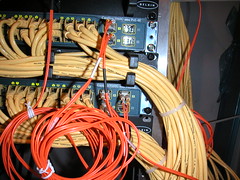
In the core we have our VLANs. As I explained in a past post each floor is a VLAN. The only way to make this physical redundancy work is to set it up virtually in the core. We have two core switches A&B. One is the root and the other is the standby. If the root core fails for whatever reason the standby is there. The setup on the core for redundant VLANs looks like this.
switch A
interface Vlan30
description CLIENT_FLOOR_30 VLAN
ip address 10.100.30.2 255.255.255.0
ip helper-address 10.100.1.22
ip helper-address 10.100.1.78
no ip redirects
no ip unreachables
no ip proxy-arp
standby 30 ip 10.100.30.1
standby 30 priority 105
standby 30 preempt
switch B
interface Vlan30
description CLIENT_FLOOR_30 VLAN
ip address 10.100.30.3 255.255.255.0
ip helper-address 10.100.1.22
ip helper-address 10.100.1.78
no ip redirects
no ip unreachables
no ip proxy-arp
standby 30 ip 10.100.30.1
This will only work if you have VTP (VLAN trunking protocol) setup obviously if you understand this far.
What is happening here is that switch A is the root and switch B is the standby. This is defined by the priority of 105.
Anywhere you see 30 represents the floor, so this VLAN would belong to the 30th floor.
The gateway of the clients on this VLAN is 10.100.30.1. Now 10.100.30.1 is on both switches and it is the HSRP (Hot Standby Router Protocol) address. So the A has a real address of 10.100.30.2 and B has a real address of 10.100.30.3 the virtual or HSRP is 10.100.30.1 and is linked to both switches by the (standby 30 10.100.30.1) command.
I'm just going over the main entries so stuff like no ip (redirect, unreachables, proxy-arp) you can google.
For VLANs the ip helper-address is important b/c broadcast do not cross VLANs (why would anyone want them to?) If you have a DHCP server that is in a SERVER VLAN just setting up the client VLANs and leaving with result in an entire network of workstation trying to find the DHCP server and not able to connect to anything. There are two simple ways to resolve this.
1. setup a DHCP server on every VLAN. This would be the dumbest and most inefficient thing to do.
2. add an ip helper-address statement (ip helper-address 10.100.1.22)to allow the client VLAN to find the server in the SERVER VLAN. 10.100.1.22 would be my DHCP server and this line would be in all my VLAN configs. Not only that but a scope for every client VLAN will have to be created in your DHCP server. So the scope created for the network on the 30th floor would be set to give out IP as such;
10.100.30.100-254 /24.
You can also see that I have another ip helper-address there. That is for another server that uses broadcasts to communicate with the clients.
For the configs above if I had a network that spanned across a 30 floor building I would have a VLAN for every floor that would look the same way. I also have a management VLAN, Server VLAN, Voice VLAN, Video VLAN, Printer VLAN, Wireless VLAN etc...
You can see how complicated this can get and this is only VLANs we are dealing with here.
No comments:
Post a Comment